The bead pack, as filler, has been introduced to thin-wall tube bending process. Consequently the bead packs can be used as fillers to improve thin-walled tube push bending process, especially the ultra-thin-wall tube bending.
The application of tube continues the trend of thinner wall significantly. The thin-wall tube bending processes play more and more important roles. For the characteristics of thin-walled structures, the thin-wall tube, especially the ultra-thin-wall tube produces the buckling and fracture easily during bending processes. Therefore, the bead pack, as filler, has been introduced to thin-wall tube push bending process. The bead pack can be considered as a kind of specific granular matter, an assembly of noncohesive spherical particles in contact. Granular matter has a rich set of unusual behavior which prevents them from being simply categorized as either solids or fluids [1], such as flowability, ‘barn effect’ [2-3], arching phenomenon [4-5], hybrid and separation under rotation and vibration [6-7], collapse phenomenon [8-9] and so on. Granular matter combines the advantages of fluids with flowability and solids with rigidities, which provides the possibility that the bead pack can be used as filler in thin-wall tube bending process. With this aim, the pressure transmission, flowing and deformation characteristics of different bead pack systems during tube bending are simulated. Here, the tube push bending process is adopted.

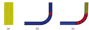
Model of Die. (c) The Model of the Whole.
Simulation
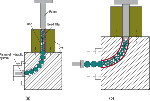
The simulations are carried out using the discrete element method (DEM), which was originally developed by Cundall and Strack [10]. The method models the interaction between contiguous balls, the balls move under the forces, and the bead pack deforms as the balls motion. The method allows the overlaps between balls, and the relationship between force and overlap follows the contact mechanics. As shown in Fig.1, under the pressure provided by the piston of hydraulic system, the punch moves down and pushes the tube and filler into the die to bend the tube. The punch and hydraulic system are considered as the boundary conditions, and the cavity of die is modeled as wall. The filler consists of an assembly of 10,000 beads. The thickness of tube is 0.3mm, and the outer diameter is 30mm. To observe the flowing and deformation characteristics of bead pack filler, the tube is considered to deform completely and perfectly, therefore ruled out. The simulations are carried out in the conditions that: linear contact model is adopted, the normal and tangential stiffness coefficients of beads are 100MN/m, and those of walls are 10GN/m; the density of beads is 8×10³kg/m3; the pressure provided by the hydraulic system is 10MPa; friction coefficients are 0 and 0.2 respectively; the filler consists of beads with the same diameter 2mm and different diameters that conforms to uniform distribution from 1.5mm to 2.5mm. The DEM model is shown in Fig.2. As the bead pack filler is pushed into the die and bent, the pressure on the bottom of punch (the top of filler) is calculated. Furthermore, in the deformation area (the red area shown in Fig.2 (b)), the pressure on the wall is also monitored.

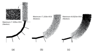
of Intercenter Connecting Segments. (a) The filler is compacted but not bent. (b) The filler is bent in the condition of frictionless.
(c) The filler is bent in the condition of friction.
Results and discussion
Under the pressure provided by the piston of hydraulic system, the punch pushes down and the filler is compacted. The interparticle contact forces inside the filler form a network of percolating force chains to resist the external load (Fig.3). Qualitatively, it can be seen from Fig.3 (b) and (c) that the pressure distribution is uniform and similar to fluid in frictionless filler, but opposite in friction. Especially, the pressure in deformation area of the filler with friction is extremely high.
Resistance to deformation
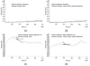
It is very important to calculate the pressure on the bottom of the punch during bending, by which the resistance of filler to deformation can be revealed. The results are shown in Fig.4. The curves in Fig.4 contain lots of vibration, in which the larger vibration is the result of the reflection of elastic wave, and the smaller is resulted by the discontinuity of difference method. It is demonstrated in Fig.4 (a) and (b) that the resistance to deformation is very small and a little higher than 10MPa (pressure provided by hydraulic system) during the bead pack filler without friction bent, whether the same size or not; For the filler contacting the large bead is bent, the contact area between the filler and large bead increases slightly, and the two curves present the tiny slope. The curves in Fig.4 (c) and (d) can be divided into three parts: 0~0.3 in Fig.4 (c) or 0~0.35 in Fig.4 (d), 0.3~0.65 and 0.65~1.0. In the condition of friction, the resistance to deformation is determined by two mechanisms which can be defined “hardening” mechanism and “softening” mechanism. Firstly, the filler in the bending cavity of die blocks the subsequent deformation under the friction, which makes bending deformation more difficult. Secondly, it can be seen in Fig.3 (c) that there is a stress gradient in the filler in the bending cavity of die. The decreasing stress in the bending cavity of die makes the whole pressure between filler and die descend, that is, the friction declines and deformation becomes easier. Under the two mechanisms, the two curves rise at first, then falls down, finally goes up. The curves in the second and third parts can be seen to rotate a certain angle versus the first part (like a nod), which can be characterized by the angle θ as shown in Fig.4 (c) and (d). Different bead pack systems have different θ.

Pressure on the wall of die in deformation area
The wall of the die in the deformation area (red area shown in Fig.2 b) is divided into four parts: the medial and lateral sides of straight-line segment, and medial and lateral sides of bending-line segment in the deformation area. During the filler bent, the pressure on the wall of die in deformation area is observed and given in Fig.5. The curves for the pressure on the wall of die in deformation area in Fig.5 present the similar shape for different parts of die and different simulation conditions. For the straight-line segment of the die in deformation area, the pressure on the medial side is slightly higher than the lateral side, but opposite for the bending-line segment of die. The bending moment which makes the filler bent is provided by the lateral side of bending-line segment of die, so the pressure on the lateral side of bending-line segment is a little higher than the medial side. Under the bending moment, the pressure on the lateral side of straight-line segment decreases and that on the medial side increases, so the situation is opposite for the straight-line segment of die.


